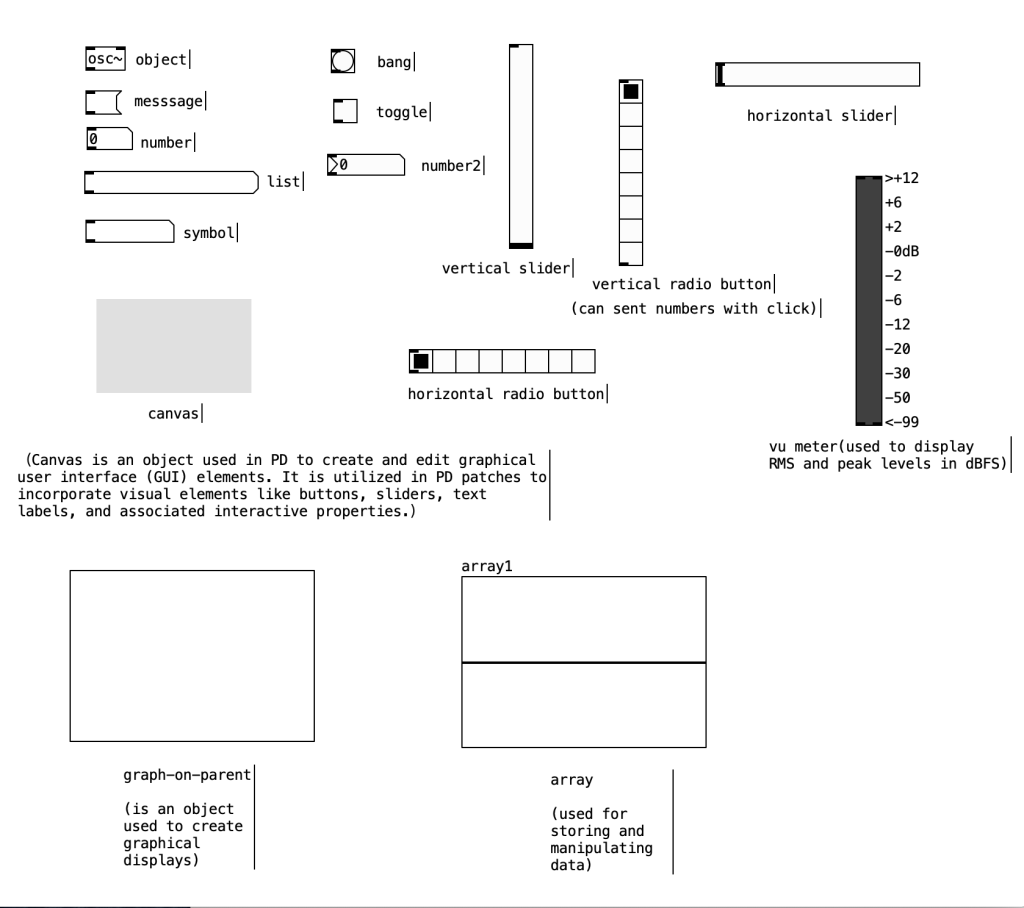
Tools in pure data
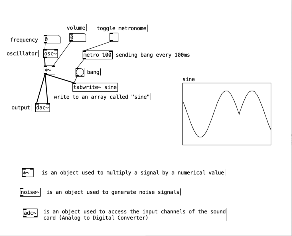
Oscillators and Oscilloscopes
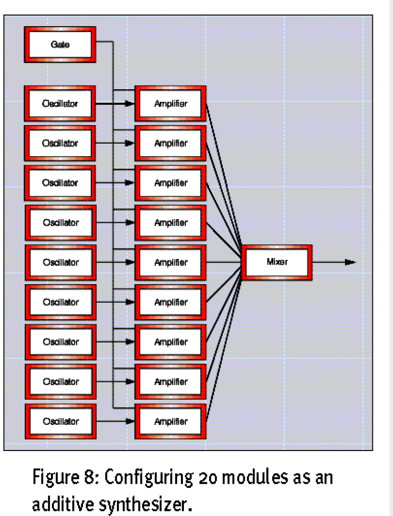
Additive Synthesis
Theory: Define the frequencies and amplitudes of different harmonics and mix them together to form a new sound.
Create on Pure Data
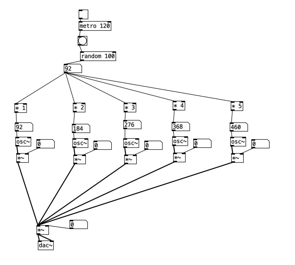
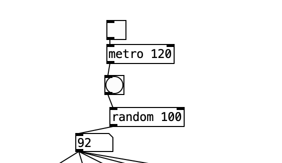
This part uses random to randomly generate any integer from 0 to 100 to control the main frequency. Toggle is the switch and metro is the speed. Sending bang every 120ms. Using this code can make the synthesizer keep playing randomly generated music.

This wave contains harmonics of all orders. The amplitude of the second harmonic is 1/2 of the fundamental wave, and the amplitude of the third harmonic is 1/3 of the fundamental wave.
Ring modulation
When the modulation technique acts directly on the amplitude input of the carrier oscillator, the modulation technique is called ring modulation. In ring modulation, the amplitude of the carrier body oscillator is determined solely by the modulating signal. Therefore, when the amplitude of the modulation signal is 0, the output of the entire ring modulation Instrument can only be 0. This feature is the most obvious point that distinguishes ring modulation from amplitude modulation.
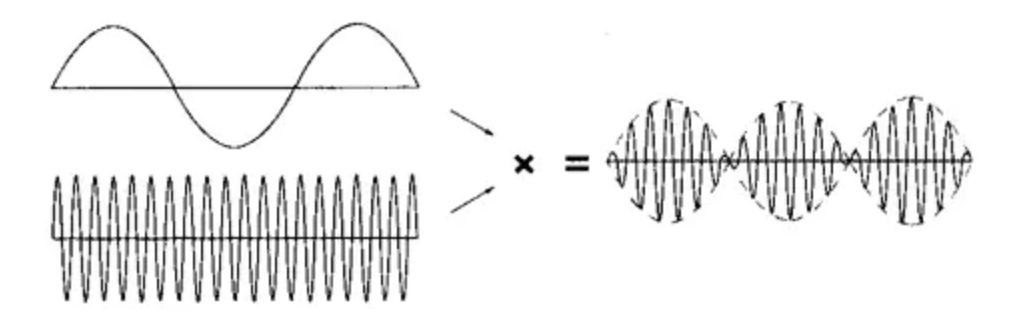
The principle of ring modulation is to combine two sound signals of different frequencies to create additional overtones.
The output of ring modulation has two important characteristics. One is that the output timbre is generally not harmonious, nor will it be harmoniously connected to any other input, except in rare cases. And importantly, neither input signal leads to the output. Another feature is that if either input is at zero volume, the output is also at zero. Because internally, the two input waveforms are multiplied.
Create on Pure Data
First, a ring modulator should consist of at least 3 parts:
The part that generates the carrier wave; the part that generates the modulated wave; the part that carries the modulated wave on the carrier wave.
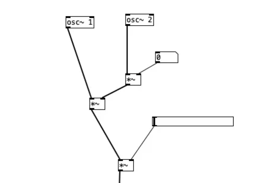
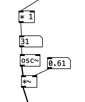
Among them, osc~ is the oscillator used to generate frequency. First, use the numbers 1 and 2 to distinguish the carrier wave osc and the modulation wave osc.
After the carrier osc1 generates the frequency, it is connected to the multiplication calculation *~ for amplitude modulation.
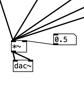
Therefore, osc~2 is linked to the right inlet of this multiplication calculation as a modulation wave. Here, another multiplication calculation is inserted, and a numerical box is inserted in the upper right to control the modulation depth and to avoid the sound explosion when the volume is too high. This will be discussed later. Connect to the multiplication calculation, connect the volume on the right, and finally connect the dac~output.
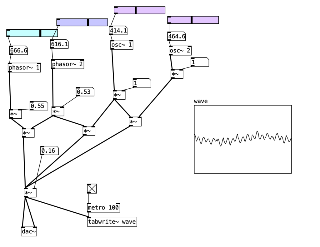
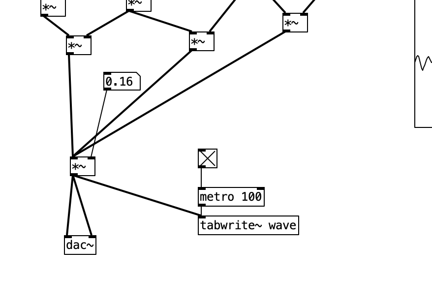
I changed the osc~ of this process to phasor~, which can produce sawtooth waves.
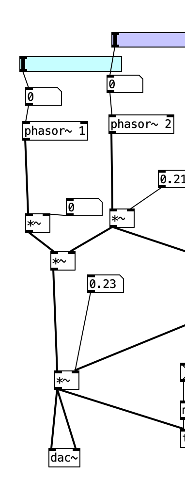
On the other side, I set up another group with osc~ as the oscillator to generate sine waves.

I also connected the middle two of these four oscillators (phasor2 and osc1) with *~, hoping that they can modulate each other to make the effect richer.
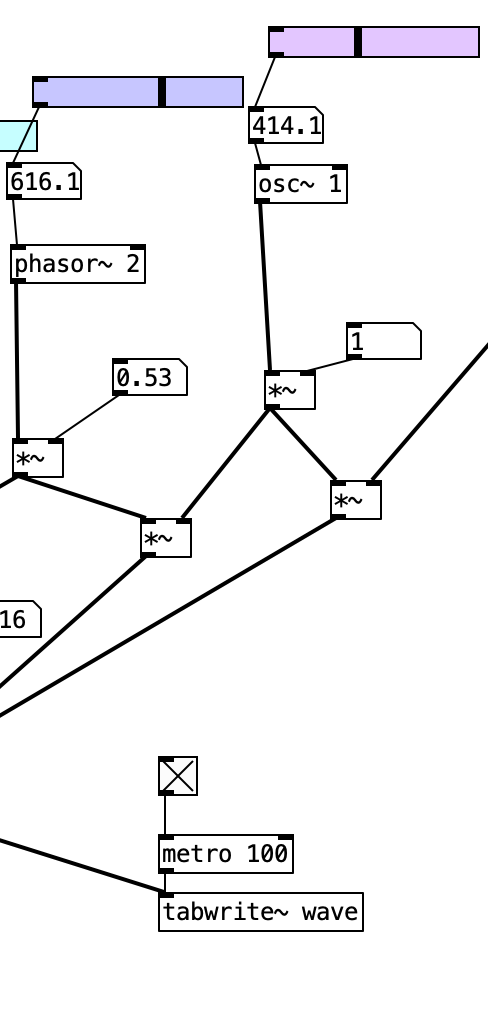
Finally I connected them to the master volume control and then output.
Final effect