- Background noise and plane noise
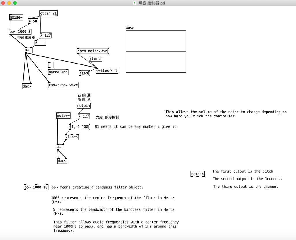
I used the keyboard knob to control the noise controller to create background noise based on the changes in the film. I saved this recording as “noise.wav” and added it to the movie clip.
2. Part of the background ambient music

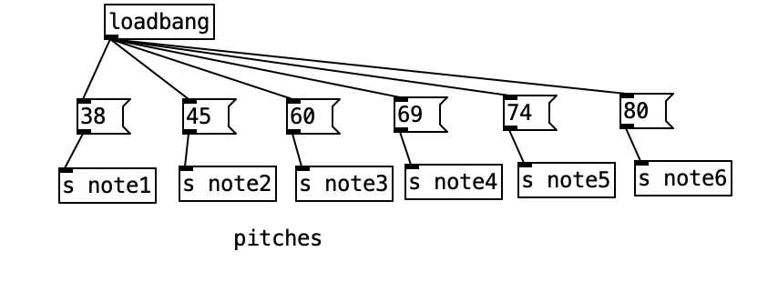
I used three sawtooth wave phasor~ oscillators, combined with three different frequency low-pass filters. The lengths of these oscillators are varied using random numbers (not less than 1000) to create a sound similar to string instruments. The pitches are set to 69, 74, and 80, respectively.
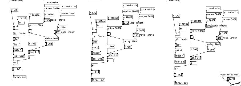
Then I duplicated this setup with three more oscillators, changing the sawtooth waves to sine wave osc~ oscillators. I modified the high-pass and low-pass filter frequencies to create oscillators with a pad-like timbre, with pitches set to 38, 45, and 60.
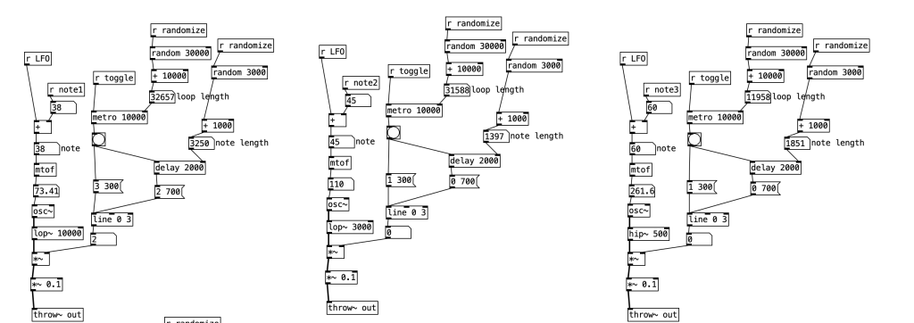
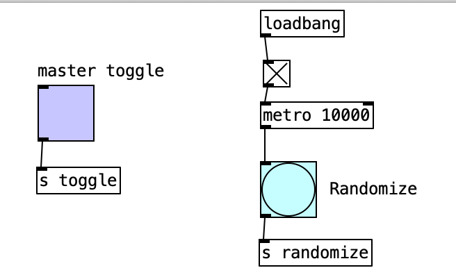
A trigger (bang) is used to control the random numbers for note length and loop length. Using a toggle combined with a metro to control a bang, allowing it to automatically trigger at a very slow pace.
After this, I added reverb. In the pad oscillator with the pitch of 38, I changed the number under delay 2000 to 2 700, ensuring a continuous low-frequency background sound.
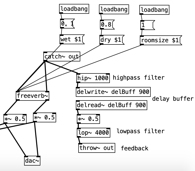
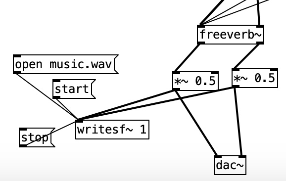
Finally, export to “music.wav”.
Reference sources:
3. Screen glitch
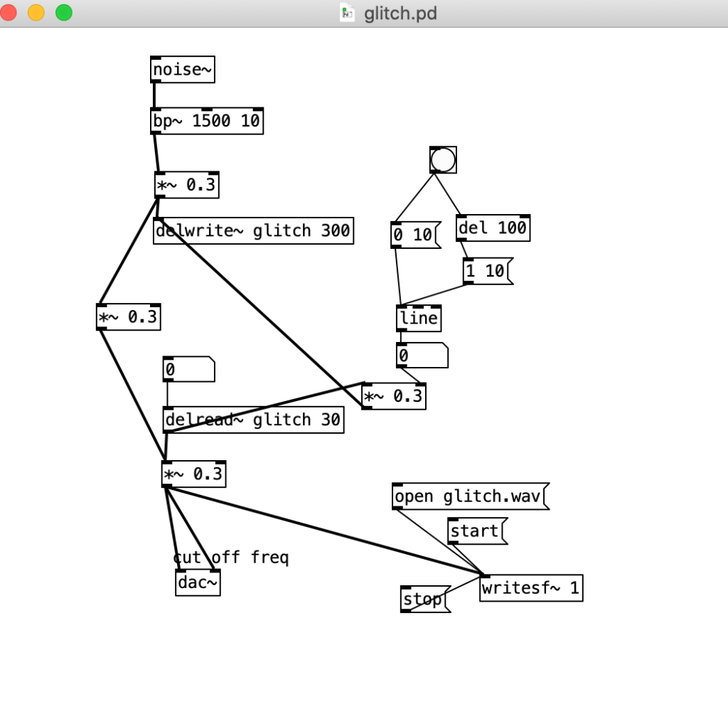
Create a looper using noise~ as the sample source, altering the length of the delay to accumulate it, thereby producing a peculiar glitch effect.
Save the appropriate clip as “glitch.wav”.
del 100: delay 100ms
delwrite~ glitch 300: Created a delay buffer named “glitch” with a size of 300 ms.
delread~ glitch 30: Read an audio signal delayed by 30 milliseconds from a delay buffer named “glitch”.
Reference sources:
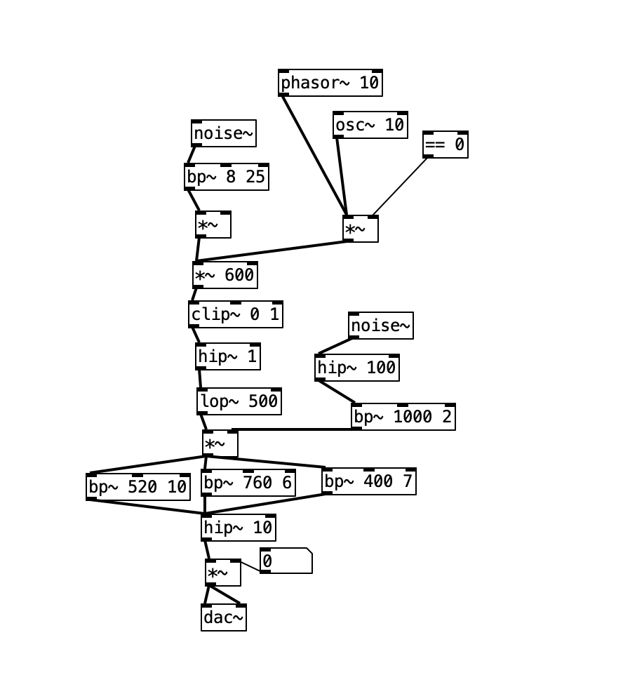
4. Car sound
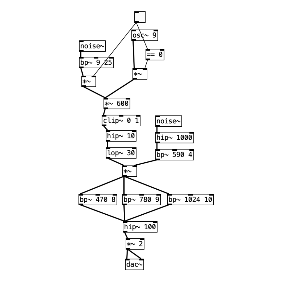
osc~ 9: An oscillator set at 9 Hz
bp~ 9 25: A band-pass filter with a center frequency of 9 Hz and a bandwidth of 25 Hz, may be used to filter out a narrow frequency range from the white noise.
hip~ 1000 & bp~ 590 4: A high-pass filter and another band-pass filter, respectively set with center frequencies of 1000 Hz and 590 Hz, and a bandwidth of 4 Hz. They may be used to further shape the frequency content of the noise.
== 0: checking if the output of the oscillator equals 0.
clip~ 0 1: limits any incoming signal to a range between 0 and 1.
hip~ 10 & lop~ 30: A high-pass filter set at 10 Hz, and a low-pass filter set at 30 Hz, are used to further shape the signal’s frequency response.
bp~ 470 8, bp~ 780 9, bp~ 1024 10: A series of band-pass filters with center frequencies at 470 Hz, 780 Hz, and 1024 Hz, and bandwidths of 8 Hz, 9 Hz, and 10 Hz, respectively. These can be used to isolate or emphasize signals at specific frequencies.
hip~ 100: Another high-pass filter, set at 100 Hz, possibly to attenuate or eliminate the lower frequency parts of the signal.
dac~: A digital-to-analog converter objec, output.
Used “noise~” and “osc~” objects, with the oscillator set to 9Hz, as the model doesn’t perform well outside of the 5Hz to 11Hz range. By switching between the noise and the oscillator, one can create an unstable sound. Amplification followed by clipping transforms the waveform into something resembling a square wave. Subsequent filters mimic an exhaust system’s outlet valve, altering the square wave into a pattern with rising and falling dynamics. The noise, high-passed around 600Hz, is then shaped into a formant filter through three parallel band-pass filters. However, if the speed exceeds 11Hz, the sound loses clarity and becomes a blur, as the technique relies on the listener’s perception filling in for the lack of real harmonic structure. As the speed increases, it becomes harder for the listener to temporally distinguish the intended engine-like events, and the illusion of the engine sound breaks down.
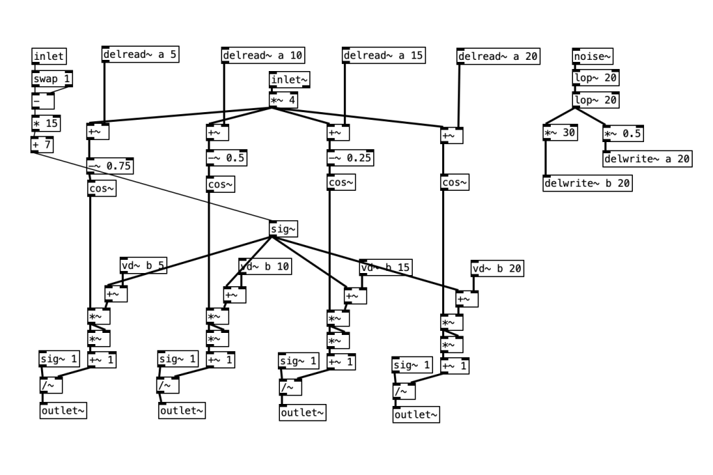
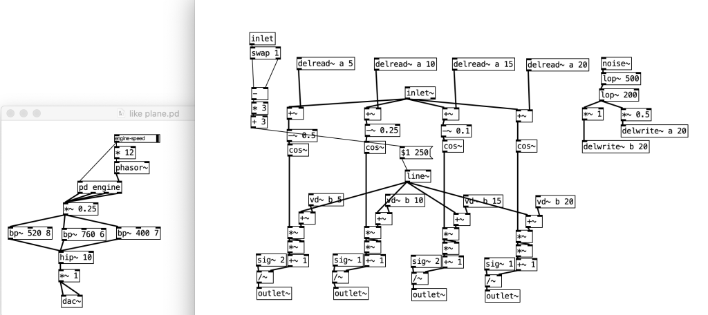
inlet and * 15 + 7: This section receives an input signal and transforms it by multiplying by 15 and adding 7.
swap 1: “swap” is a built-in object used to swap the positions of two numbers. swap 1 means that the object is set up to swap its two inputs.
delread~ a [5, 10, 15, 20]: These four objects read signals delayed by 5, 10, 15, and 20 milliseconds from their respective delay lines named ‘a’.
cos~: This converts the received signals (after subtracting 0.75, 0.5, 0.25) into a cosine waveform.
+~: This object performs a phase shift on the output of the cosine waveform to simulate the combustion sequence of each engine cylinder.
vd~ b [5, 10, 15, 20]: These four objects read from delay lines named ‘b’, which is part of adding jitter to timing and pulse width.
noise~: Generates white noise, filtered through two low-pass filters lop~ 20 to produce noise around 20Hz.
*~ 30 and *~ 0.5: These objects adjust the amplitude of the noise signal to fit the delay lines.
delwrite~ a 20 and delwrite~ b 20: These two objects write signals to delay lines named ‘a’ and ‘b’ for subsequent delread~ and vd~ read operations.
sig~: This object is for further signal processing.
~: This symbol indicates amplification a signal.
outlet~: This is an output object, to send the processed signal to other objects.
This is achieved by creating four copies of a process that shapes a waveform using a mathematical formula (1/(1 + kx^2)), fed by a cosine wave. These copies are phase-shifted relative to each other by subtracting fractions of a cycle from their inputs, yielding four distinct phases from the same phasor.
An element critical to the realism of the patch is the introduction of timing and pulse width jitter, which is accomplished by feeding a noise source filtered to around 20Hz into two delay lines at different levels. Delays spaced 5ms apart simulate the effect of fuel and air feeding into each cylinder one after the other, creating a ripple of jitter across the cylinders for a realistic sound.
Additionally, the patch includes small amounts of noise to alter the pulse width and firing timing, creating subtle effects. The pulse width is also modulated based on the engine speed; it’s narrower at low speeds, which includes more harmonics, and widens as the engine speeds up. This modulation not only prevents the engine sound from becoming too harsh at higher speeds, where aliasing could occur, but also simulates the low-pass filtering effect of exhaust impedance.
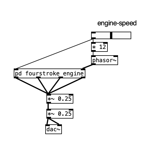
engine-speed: Control the simulated engine speed.
* 12: This object multiplies the engine speed by 12. This could be part of the calculation to convert the user-controlled speed into a frequency that the phasor~ can use. Given that the top speed of the engine is 40Hz representing 2400RPM, multiplying by 12 suggests that each increment on the engine-speed control represents 200RPM.
phasor~: This is an oscillator that generates a ramp waveform. Here, it’s being used to drive the timing of the engine simulation. The frequency of the phasor~ controls how fast the engine “runs.”
pd fourstroke_engine: This is a subpatch that contains the logic for simulating a four-stroke engine.
*~ 0.25: Scaling down the volume signal by a factor of 0.25.
dac~: Output
Each of the four cylinders has an outlet, and the engine’s speed is controlled by an external phasor, which is subject to a low-pass filter. This low-pass filter introduces the effect of inertia into the simulation, reflecting the physical limitation of mechanical systems which cannot speed up or slow down instantaneously. It emphasizes that sound design for engines should consider this inertia to avoid unrealistic changes in speed. The maximum speed of the engine is set to 40Hz, which translates to 2400 revolutions per minute (RPM). Due to the four cylinders, the top speed will produce an auditory perception of pulses at 160Hz.
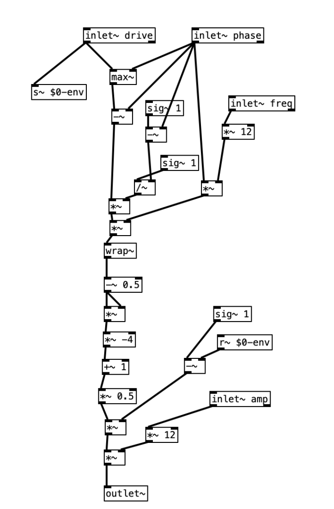
inlet~ drive: This inlet accepts a driving signal
max~: This object could be used to set a maximum value for the incoming signal, ensuring it doesn’t exceed a certain level.
inlet~ phase: This inlet is used to introduce a phase shift to the driving signal.
inlet~ freq: This inlet controls the frequency of the simulation, which is then multiplied by 12, to scale it to the appropriate range for sound synthesis.
*~: for defining the amplitude and frequency characteristics of the resulting sound.
wrap~: This object wraps the signal back within a specified range, often used to create repeating waveforms or to manage signals that exceed a given amplitude.
sig~/~: These objects are signal arithmetic operators that perform division and multiplication on the incoming signals.
~ 0.5 and *~ -4 +~ 1 *~ 0.5: This sequence of operations appears to apply a parabolic transformation to the input signal, as described in the previous text summary. The goal is to convert a linear phasor into a curved one, which is then used to generate the engine pulses.
inlet~ amp: This inlet controls the overall amplitude of the sound, which is then multiplied by 12, indicating a significant scaling up of the signal.
outlet~: This sends the processed signal out of the patch.
The system utilizes four inputs: a driving phasor (d), a phase shift control (p), a frequency control (f), and an amplitude control.
The driving phasor is adjusted by a phase value between 0.0 and 1.0, which, when subtracted from the phasor, resets the starting point to zero. To maintain the correct scaling, it is then normalized by multiplying with 1/(1 – p). After this, the signal is scaled further by multiplying by 12pf, which amplifies the curve beyond the value of 1 in accordance with the current phase.
The next step is modulating it with the complement of the original phasor. This results in short, decaying pulse bursts. The phase and frequency of these pulses can be independently adjusted, allowing for precise control over the additional noises like clanks or knocks that might occur on each turn of the engine. The controls also allow for the adjustment of the tone, intensity, and position of these sounds.
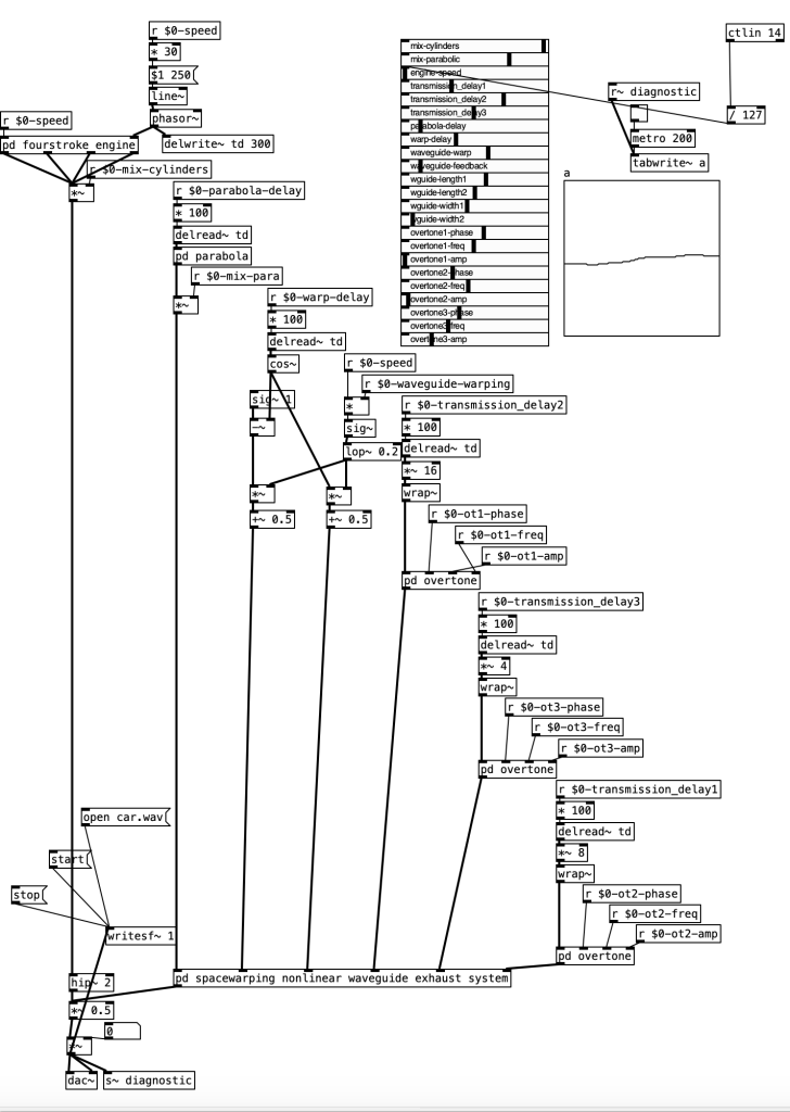
[pd fourstroke_engine]: This subpatch likely simulates the sound of a four-stroke engine. It receives control signals for speed and uses them to generate the engine sound.
[delwrite~ td 300] & [delread~ td]: These objects form a delay network used for creating echo or reverberation effects, which can simulate the acoustics of engine parts.
[pd $0-mix-cylinders] & [pd $0-mix-para] & [pd $0-wrap-de-lay]: These are subpatches that likely process the individual cylinder sounds, mixing them together, applying a parabolic wave shaping, and handling phase wrapping, respectively.
[pd overtone]: Multiple instances of this subpatch suggest it’s adding harmonic content to the engine sound, simulating the complex frequencies produced by an engine.
[r $0-*]: These receive objects are getting control signals for different parameters like phase, frequency, and amplitude, which are likely used to modulate the overtone subpatches.
[metro 200] & [tabwrite~ a]: These objects are used for timing and recording data at regular intervals, possibly for diagnostics or visualization.
[open car.wav], [writesf~ 1], [hip~2]: These objects suggest the patch can play back a .wav file, record the output, and apply a high-pass filter to remove low-frequency rumble.
[pd spacewrapping nonlinear waveguide exhaust system]: This subpatch might simulate the sound of the car’s exhaust by manipulating the waveguide properties non-linearly.
[ctlin 14] & [r~ diagnostic]: These are used for receiving MIDI control data.
[dac~]: This is the digital-to-analog converter object, the final output for the audio signal to be sent to the speakers.
Set 23 controls
• Cylinder mix- the level of the four cylinder engine model
• Parabolic mix- level for vibration of the whole engine
• Engine speed–main engine frequency
• Transmission delay 1—time delay to first overtone
• Transmission delay 2—time delay to second overtone
• Transmission delay 3—time delay to third overtone
• Parabola delay—relative shift of pistons to engine movement
• Warp delay—move the nonlinearity up and down the exhaust
• Waveguide warp—the amount of FM applied in the waveguide
• Waveguide feedback-liveness of the pipe resonance
• Waveguide length 1- first quadrant delay time
• Waveguide length 2- second quadrant delay time
• Waveguide width 1-third quadrant delay time
• Waveguide width 2– fourth quadrant delay time
• Overtone 1 phase offset of excitation 1 relative to cycle
• Overtone 1 freq-maximum spread of first excitation spectrum
• Overtone 1 amplitude- amplitude of first excitation
• Overtone 2 phase offset of excitation 2 relative to cycle
• Overtone 2 freq- maximum spread of second excitation spectrum
• Overtone 2 amplitude-_amplitude of second excitation
• Overtone 3 phase- offset of excitation 3 relative to cycle
• Overtone 3 freq–maximum spread of third excitation spectrum
• Overtone 3 amplitude amplitude of third excitation
Reference
Farnell, A. (2010) Designing sound. Cambridge, MA: MIT Press.
5. Plane Noise
6. Tinnitus-like sound
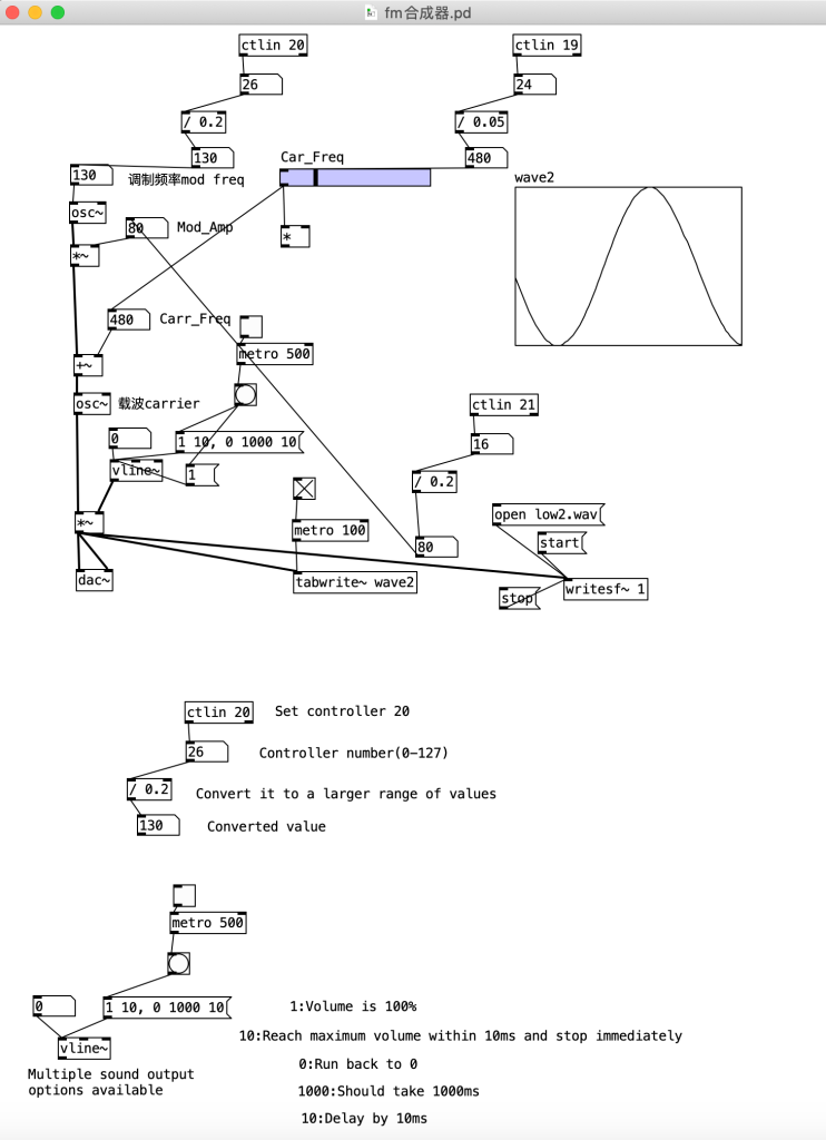
This synthesizer was mentioned in the previous “pure data learning” blog. I used three knobs to modulate each other to find a very high frequency and recorded it as “low2.wav”.